
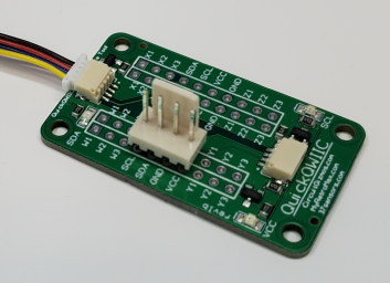
The CircuitGizmos QuickQWIIC interface board lets you interface various modules to the QWIIC bus. It is a great way to make any I2C module/board into a Qwiic-enabled board. The QWIIC interface can be found on various development boards.
The QuickQWIIC has dual QWIIC headers on the board to facilitate a daisy-chain from the controlling QWIIC device to other QWIIC devices. Several boards can be chained together to put more than one I2C device on a bus. In the center of the QuickQWIIC are rows of plated-through holes with the four connections of QWIIC (power, ground, data, clock) arranged in different order to make connecting to I2C modules with their own arrangement of these signals easier.
If you have an I2C module with a 4 pin header that has power, ground, data, and clock in that order it is easy to find those pins on the QuickQWIIC in that same order. If power and ground are swapped, there is a row on the QuickQWIIC that will support that.
You can order a QuickQWIIC bare board or a board with the surface-mount parts populated. A third option includes a selection of .1" header sockets.
The red board in the images is an I2C module attached to the QuickQWIIC in the appropriate place for the order of the power, ground, data, and clock signals. By being plugged into the QuickQWIIC board this PCF8574A Remote 8-Bit I/O Expander becomes a QWIIC bus peripheral.
The blue board in the images is an RTC module (DS1307) with an EEPROM (24C32). The QuickQWIIC board makes this module a QWIIC bus peripheral. The BAT connection of the board lands in the Z1 position on the QuickQWIIC board. A jumper wire inserted into the other Z1 position can be used to connect to an external battery for this module. There are 12 pairs of these utility connections on the QuickQWIIC module.
Other connectors that have a pin spacing of .1" can also be used with the QuickQWIIC.
